
This simple fingerprint door unlock project using Arduino can be very useful for door security, forensics, crime investigation, personal identification, attendance systems and much more. In the future, there could be many more applications like fingerprint-based driving licenses, bank account operations and so on.
The whole system works under a simple algorithm called the matching algorithm, which is used to compare previously stored templates of fingerprints against users’ fingerprints for authentication purposes.
A key is normally used for traditional door opening, but it provides very poor security. In this fingerprint door unlock project, only when an authorized person places a finger on the sensor, does the door unlock and the LCD displays a welcome message along with that person’s name.
Circuit and working
The circuit shown in Fig. 1 operates using a 12V power supply. An Arduino microcontroller (MCU) requires only 5V but the solenoid electric lock requires 12V. As Arduino Uno has an inbuilt 5V voltage regulator, a common 12V supply can be used for the whole system.
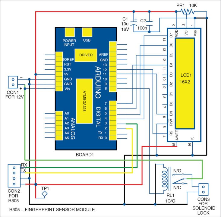
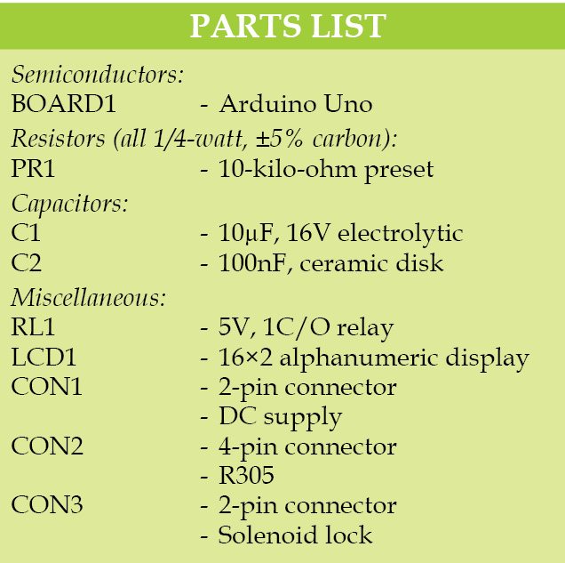
The brain of the circuit is the Arduino Uno MCU board (BOARD1). It is based on ATmega328/ATmega328P and has 14 digital input/output (I/O) pins, six analog inputs, 32k flash memory, 16MHz crystal oscillator, a USB connection, a power jack, an ICSP header and reset button, among others. It can be programmed using Arduino IDE software.
Fingerprint sensor module R305 (connected across CON2) has a UART interface with direct connections to the MCU or to the PC through a max232/USB serial adaptor. The user can store fingerprint data in the module and configure it in 1:1 or 1:N mode for identification. Pins TX and RX of R305 sensor are connected to Arduino digital pins 2 and 3, which are used for serial communication.
The LCD display (LCD1) is used to display messages during action. Here, a 16×2 display is used; each character is made of 5×7 dot-matrix. Pins 3, 4, 5, and 6 of the LCD are the control lines connected to preset (PR1) output, pin 12 (Arduino), GND, and pin 11 (Arduino). Pins 11, 12, 13, and 14 are data pins of the LCD that are connected to pins 7, 6, 5, and 4 of Arduino, respectively. Preset PR1 is used to adjust the contrast of the LCD display.
An electronic door-lock solenoid (connected across connector CON3) is basically an electromagnet made of a big coil of copper wire with an armature (a slug of metal) in the middle. When the coil is energized, the slug is pulled into the center of the coil. This allows the solenoid to move to one end.
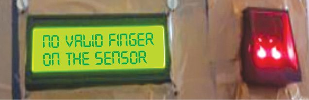
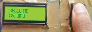
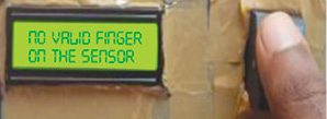
The solenoid lock requires more current than what Arduino can provide. Therefore to operate the lock, a 5V relay (RL1) is used. CON3 is connected between normally open (N/O) contacts of RL1 and GND. The sequence of messages on the LCD from the author’s prototype is shown in Figs 2, 3, and 4.
Software
Programs named enroll and fingerprint use different functions like getFingerprintEnroll(int,id), Adafruit_Fingerprint(&mySerial) and getFingerprintEnroll(id). These functions are defined inside the library and pass arguments when called.
After uploading enroll in the Arduino, and open the serial monitor from Arduino IDE from Tools→Serial monitor options. Change the baud rate below the serial monitor window to 38400. Choose the Newline option from the same place. Then, follow the instructions on the serial monitor. Place the finger on the fingerprint module. Type any whole number as the ID number. Press the Send tab to send the ID number from the serial monitor to Arduino. This fingerprint gets converted into digital data and gets stored inside the R305 module database.
More than 200 fingerprints can be stored on this system. Make sure that each fingerprint has a unique ID number. This ID number will be used in the next program to identify the authenticated person’s name. The serial monitor will guide the user as to when he or she should place the finger and when to remove it.
For debugging without an LCD, make the same settings for the serial monitor after uploading the Fingerprint program. This is used to compare the fingerprint in the sensor with stored prints. The serial monitor guides here also. The fingerprint program should be edited to change the name and ID numbers according to user preferences.
Download source code: click here
Construction and testing
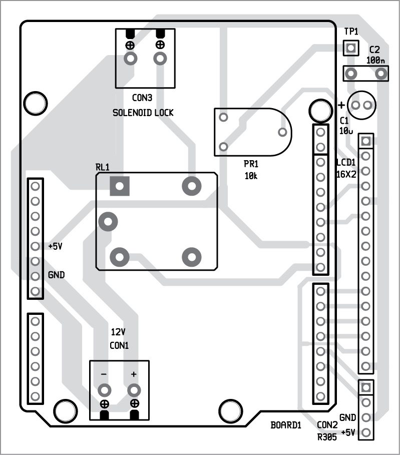
The single-side PCB for the fingerprint door unlock system is shown in Fig. 5 and its component layout is in Fig. 6. For convenience, we have designed the PCB as an Arduino shield. Users can modify the design as required. Also, they can test PCBs with an Arduino board using a cable connector.
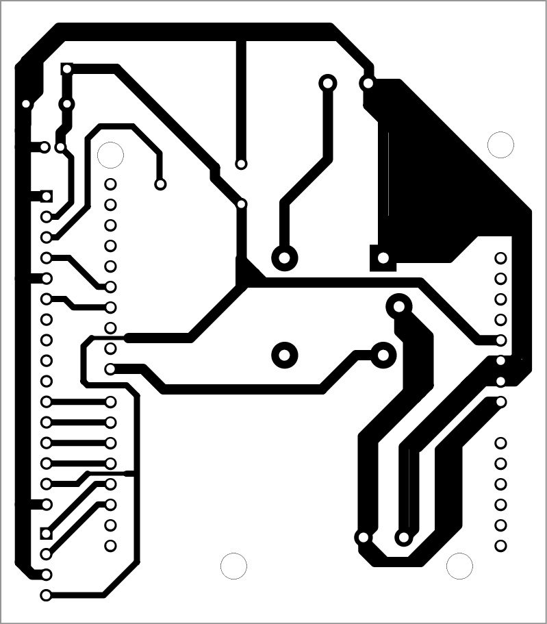
Download PCB and component layout PDFs: click here
Make sure the baud rate given in the program is correct. The baud rate for the serial monitor can be anything but the baud rate for the R305 sensor should match that given in its datasheet. The baud rate may vary with different versions of the sensor. It is given in the program like Serial begin(38400) [baud rate for serial monitor]; finger.begin(57600) [baud rate for sensor]. Reset the Arduino board before the fingerprint is validated.