Where to use LM3914?
The LM3914 is an analog controlled, meaning it can control (turn on or off) 10 LED lights based on an analog input voltage. This IC eliminates the need for microcontroller and programming and also reduces the hardware required to control 10 LEDs.
The analog input voltage can vary from 3V to 18V and the LED current can be limited by simply using a single resistor on pin 7 (Ref Out). The IC also has two operating modesand, also more than one IC can be cascaded to control upto 100 LEDs. Since the LEDs can be controlled without any flickering and flawlessly with equal brightness these IC’s are commonly used in visual alarms and other metering/monitoring applications. So, if you are looking for an IC to driver your bar LED lights or other sequence of 10 LED then this IC might be of interest to you.
How to use a LM3914?
The advantage of using LM3914 is that it requires minimum hardware and can be easily set up. We simply have to connect the 10 LEDs to the IC, set the reference voltages for input voltage and limit the current through the LED and we are all set
Simply power the IC using the V+ and V- and the analog signal voltage is given to pin 5. Here we have used 9V to power the IC to monitor an analogy voltage of 0-5V. Always note that the voltage used to power the IC (here 9V) should be at least 1.5V more that the monitoring voltage(here 5V).
Since we are monitoring 0-5V here, the low reference voltage (pin 4) is set at 0V and the high reference voltage (pin 6) is set to 5V. As you might have noticed we have connected all the 10 LEDs directly to the IC without any current limiting resistor this is because the IC has an internal current limiter and the value of current can be set by using the pin VRO (pin 7). The formulae to calculate the current is given below, where I is the current through each LED and RL is the resistor connected to pin 7.
I = 12.5/RL
In the above example we have used a 470 ohm resistor as Rl and hence the current through each LED will be around 25mA, you can modify the value as required. Also note that the cathode of the LED is connected to IC and anode is connected to +5V. This is because the IC output pins can only sink current and cannot source it.
The IC can operate in two different modes, one is the dot mode and the other is bar mode. In dot mode the mode pin (pin 9) has to be left floating, in this mode only one LED will be turned on based on the input voltage. In Bar mode the mode pin (pin 9) has to be connected to V+ and in this mode the LED will turn on or turn off sequentially based on the input voltage. Both the modes are shown in the gif file above.
Applications
- Crude Battery level indicators
- Low cost monitor devices
- Digital gauges
- Electronic displays
- Fade bars
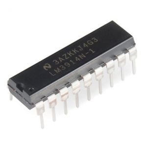
LM3914 Pin Configuration
| Pin Number | Pin Name | Description |
| 1 and 10 to 18 | LED1, LED2, LED3…..LED10 | The 10 LEDs which has to be controlled is connected to these pins |
| 2 | V- / Ground | Ground pin of the IC |
| 3 | V+ / Vcc | Supply Voltage (3-18)V |
| 4 | RLO | Low level voltage for potential divider |
| 5 | Signal | Analog signal Input pin based on which the LED is controlled. |
| 6 | RHI | High Level voltage for potential divider |
| 7 | REF OUT | Output Reference Voltage for LED current limiting |
| 8 | REF ADJ | Adjust pin for voltage reference |
| 9 | Mode | Select between Dot/Bar Mode |


Reviews
There are no reviews yet.