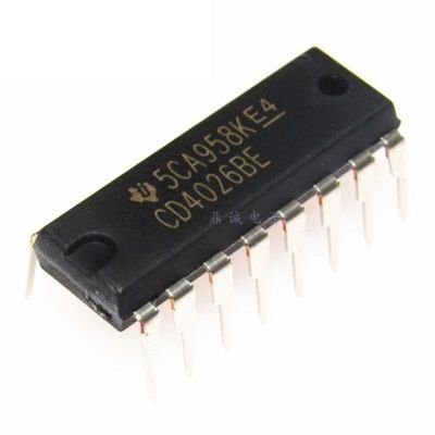
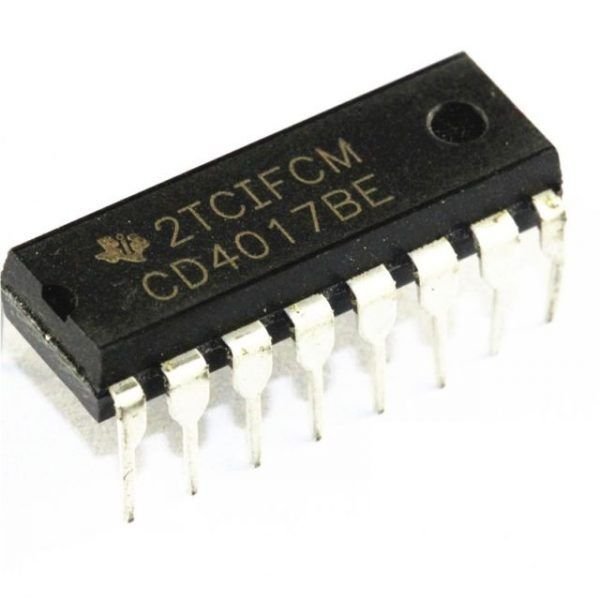
CD4026 7 Segment Counter
CD4026 7 Segment Counter is a 4000 series IC. This is a CMOS seven-segment counter IC and can operate at very low power. Its a decade counter, counts in decimal digits (0-9). It is use to display numbers on seven segment displays and it increments the number by one when a clock pulse applies to its PIN 1
Means more the clock pulse rate, faster the numbers change in 7 Segment Display. Below is the pin diagram and pin description of 4026 IC:
CD4026 7 Segment Counter Pin Configuration:
| Number | Name | Description |
| 1 | Clock (CLK) | The counting happens when this clock pulse goes high, this pin is normally connected to 555 timer or other uC to produce a pulse |
| 2 | Clock Inhibit (INH) | Connected to the Ground (low) of the circuit, to enable clock pin |
| 3 | Enable Input (DEI) | This pin is connected to +5V (high) to enable the output pins (Out A to Out G) |
| 4 | Enable Output (DEO) | This is an output which always stays high, this pin will be only if more than one CD4026 IC is used (cascaded) |
| 5 | Divide by 10 (CO) | This is the carryover output pin; it produces a pulse after counting till 9. This pin will be only if more than one CD4026 IC is used (cascaded) |
| 6,7,9,10,11,12,13 | Out A,B,C,D,E, F,G | These are the decoded output pins which must connect to 7-Segment display. |
| 8 | Ground | The ground pin must connect to the ground of the circuit |
| 14 | Not 2 out (UCS) | This is Ungated C segment pin. This is an output pin which will rarely use when division is require. |
| 15 | Reset | This input pin when make high (+5V) will reset the count to 0. |
| 16 | VCC | This pin powers the IC, typically +5V is use. |
Features:
- Counter for 7-Segment display
- Can drive a common cathode 7-Segment display directly
- Easy to interface with a timer or micron rollers (TTL compatible)
- Can easily cascade with more IC to display the higher range of number
- Maximum Clock Frequency: 6Mhz
Where to use
The IC CD4026 is an IC which can perform the function of both a counter as well a 7-segment Driver. One single IC can use to count form zero (0) to nine (9) directly on a Common Cathode type 7-segment display. The count can increase by simply giving a high clock pulse; also more than one digit (0-9) can create by cascading more than one CD4026 IC. So if you have a 7-segment (CC) display on which you have to display numbers that are being counted based on some condition then this IC will be a perfect choice.
How to use
The IC can work from 3V to 15V, but normally power with +5V to the VDD/VCC pin and the Ground/VSS pin is connected to ground. We have 7 output pins naming from Out A to Out G which is directly connected to the 7-segment display. The clock inhibits pin (pin 2) is held low (ground/0V) so that the clock signals can send to the IC also the Enable Input pin (pin 3) make high (+5V) so that the output pins (Out A to G) can active.
The 7-segment pins will increment the count by one number each time when the clock pin (pin 1) is made high. This clock source can either be obtained from a 555 IC or any other digital IC which is TTL compatible. They simply have to generate a pulse of low voltage 0V and high voltage 5V. In the circuit below I have used a clock source of 1Hz to increment the count.
Reset Pin
The Reset pin (pin 15) is use to reset the count back to zero when made high. There are three other output pins (pin 5,4,14) which will use only when the IC needs to be cascaded. The pin Carryover (CO pin 5) will stay high by default, but when the count reaches 9 it will give a small pulse and count will continue from 0 again. This small pulse can also use to drive the clock pin of a cascaded IC to display more than one digit. The Direct Enable output (DEO) pin will always stay high, to enable any cascaded IC, if available. The Ungated C segment pin (pin 14) is use for any division operation; this pin will stay high by default and will go low when the count reaches 2.
Applications
- Use in 7-segment counter projects
- Can use to count people or objects crossing a point
- Has the capability to display a wide range of numbers from 0 to 999
- Use in the project where Microcontrollers are to avoid.
Data Sheet:
Package Include:
1 X CD4026 7 Segment Counter


Reviews
There are no reviews yet.