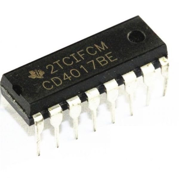
CD4017 Decade Counter
CD4017 Decade Counter is a CMOS Decade counter and it is used in the applications of low-range counting. This IC will count from 0 to 10 and the circuit with an IC 4017 will save board space as well as the time necessary to design the circuit. This decade counter is similar to Johnson 10 stage decade counter. This CMOS IC is frequently used in designing the 10 LEDs-based circuits to run the light for beginners. So it is one of the most flexible counters because it counts up to 10 & also it includes 10 separate outputs. This IC includes the counter as well as the decoder.
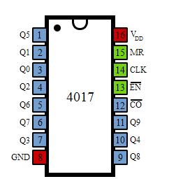
Pin Configuration of CD4017 Decade Counter
A CMOS decade counter like 4017 IC includes a five-stage Johnson counter & 10 decoded outputs for counting up to 10 decimals. This IC can be used in different counter circuits such as an LED chaser light & also a non-contact circuit with an AC detector. This IC includes 16 pins where 10 & 16 pins are output pins. This IC counts for every positive otherwise increasing edge input provided at the CLK input.
Here, the output begins from 0 and moves to output 9. Once it reaches then the output will count at 9 and again it repeats from 0 & continues this revolution similar to a ring counter. On each count among 0 to 9, the particular output pin can include a high state & the remaining output maintains low; simply one o/p will be high at a time.
For instance, if the count is presently three then the output at pin-7 is will be in a high state whereas the remaining pins are in a less state. If two cycles of the square wave are applied toward the clock input, then the output will shift to output 4 on the positive edge of the primary cycle which alters output-4 to high state & output-3 to low state.
Now the condition remains until another positive edge of the next cycle arrives, after that the o/p moves to pin1 or output 5 and maintains this condition. The ic 4017 internal structure is shown below.
Features & Specifications of CD4017 Decade Counter
The main features and specifications of IC 407 include the following.
- The supply voltage of IC 4017 ranges from 3V to 15V, usually +5V
- This IC is well-matched with Transistor-Transistor Logic or TTL.
- The operational speed/CLK speed of this IC is 5 MHz.
- It provides support to10 outputs that are decoded.
- It is available in different packages like 16-pin GDIP, PDIP & PDSO
- Input high time 30 ns
- Output current is 10 mA
- Noise immunity is high typically 0.45 VDD
- Operation is completely static
- Low power like 10 W
- Speed operation is medium like 5.0 MHz with 10V VDD
- Input Voltage or Vin ranges from 0.5 VDC to VDD +0.5 VDC
- TS or Storage Temperature ranges from 65C to +150C
- VDD or DC Supply Voltage ranges from 0.5 VDC to +18 VDC
- PD or Power Dissipation is Dual-In-Line is 700 mW
- TL or Lead Temperature is 260C


Reviews
There are no reviews yet.